
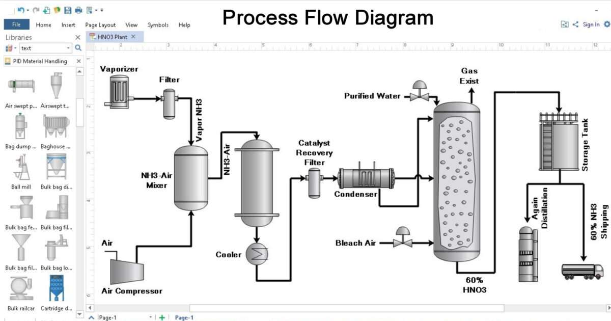
It illustrates the general plant streams major equipments and key control loops. Process topology stream information and equipment information.

The Comprehensive Guide Process Flow Diagrams Process Flowcharts Gliffy By Perforce
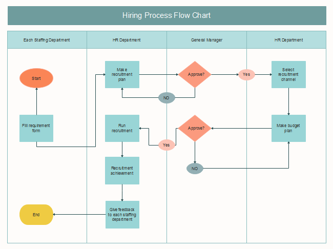
Free Hiring Process Flow Chart Templates

File Process Flow Diagram For The Extraction Of Tungsten From Wolframite Ore Png Wikimedia Commons
Chemical and Process Engineering Solution from the Industrial Engineering Area of ConceptDraw Solution Park is a unique tool which contains variety of predesigned process flow diagram symbols for easy creating various Chemical and Process Flow.
Process flow diagram. You should create your process flow diagram so that it focuses on major plant processes and not show minor details. It uses defined symbols like rectangles circles and arrows plus short text labels to show data inputs outputs storage points and the routes between each destination. It usually doesnt show exceptions or problems that may occur during the process flow.
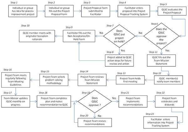
USE THIS TEMPLATE Process diagramming can play a role in optimizing and communicating about any internal process especially for complex processes that change often or that involve several people. The lifecycle of asset management process flow diagram begins with a plan and it is developed for optimization of firms financial assets to ensure delivery of agreed standard of services. Make your own Process Flow diagrams with this FREE online drawing tool.
The concept of the process flow diagram was first pointed out by Frank Gilbreth an American industrial engineer in the 1920s. It should be split into major processes which give greater detail and each major process may further split to give more detail. Process Flow Diagram is a simplified sketch that uses symbols to identify instruments and vessels and to describe the primary flow path through a unit.
What is a Flowchart. Process flow diagrams PFDs are used in chemical and process engineering. PFDs are used for visitor information and new employee training.
Block Flow Process Diagram. A business process flow diagram is the simplest and most primary representation of processes. A PFD does not show minor components piping systems piping ratings and designations.
2 In the second definition the meaning is limited to the representation of the physical route or flow. A PFD should include. Generally a Process Flow Diagram shows only the major equipment and doesnt show details.
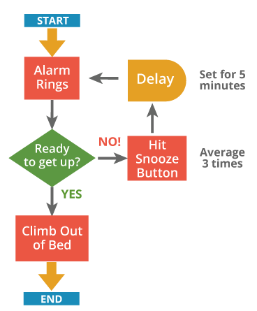
Or a flow process chart can act as a step-by-step blueprint that helps an employee perform a specific task like this Smart diagram guide to troubleshooting billing problems. This model will concentrate on a particular sectorarea of a chemical plant. A process flow diagram PFD also known as a flowsheet is a type of flowchart used by chemical and process engineers to illustrate high-level processes.
A process flow diagram PFD is a diagram commonly used in chemical and process engineering to indicate the general flow of plant processes and equipment. A data flow diagram DFD maps out the flow of information for any process or system. This chart is similar to operation process chart with the difference that it utilizes symbols of operation.
The process flow diagram is divided into three sections. It conveys a process and the path of its individual components - therefore it is essential to learn how to read and create one. Download Process Flow PowerPoint Templates to describe your processes with outstanding designs that will impress your audience.
Another commonly used term for a PFD is flowsheet. Use this video tutorial to learn how to draw business process flow diagram using Microsoft Visio. A flow process chart is a chart showing the sequence of the flow of a product by way of recording all activitiesevents under review with appropriate symbols.
Process flowchart process flow diagram. Usually more than one asset is managed with an asset management plan and it also takes a system approach. These diagrams show the flow of chemicals and the equipment involved in the process.
Its used to document a process improve a process or model a new one. A process flow diagram is a flowchart that depicts the relationships between major components in a process or circuit. Select copy and paste the components you want to use.
They also provide detailed massenergy balance data along with stream composition and physical properties. The process flow diagram is an essential part of chemical engineering. Process Flow Diagram PFD is a commonly used chart in chemical engineering and process engineering demonstrating the ongoing production flow of chemicals and other types of equipment involved.
Its most often used in chemical engineering and process engineering though its concepts are sometimes applied to other processes as well. Business Process Flow Diagram is a graphical presentation of business processes and process flows. A Process Flow Diagram PFD is a type of flowchart that illustrates the relationships between major components at an industrial plant.
Flow diagram is a graphic representation of the physical route or flow of people materials paperworks vehicles or communication associated with a process procedure plan or investigation. A Process Flow Diagram - PFD - or System Flow Diagram - SFD shows the relations between major components in a system. It is one of the main tool of business analysis and business process re-engineering that lets identify and easy understand process flows within organization.
The PFD displays the relationship between major equipment of a plant facility and does not show minor details such as piping details and designations. Browse process flow diagram templates and examples you can make with SmartDraw. A context diagram gives an overview and it is the highest level in a data flow diagram containing only one process representing the entire system.
You can get a piece of actionable advice on where you need to focus your efforts in order to improve your process in a single glance. PFD also tabulate process design values for components in different operating modes typical minimum normal and maximum. A process flow diagram PFD is a diagram used in chemical and process engineering to indicate the general flow of plant processes and equipment.
Ranging from different styles and shapes linear circular spiral geared futuristic etc our editable presentations allows the user to fully customize their process flow adding proprietary information and altering the flow as needed. Macro flowchart top-down flowchart detailed flowchart also called process map micro map service map or symbolic flowchart deployment flowchart also called down-across or cross-functional flowchart several-leveled flowchart. The concept originated in 1921 - it was designed by industrial engineer Frank Gilbreth.
FREE online Process Flow Diagram drawing template - enabled for the FREE online Google Docs. ConceptDraw DIAGRAM extended with Business Process Workflow Diagrams solution from the Business Processes area of ConceptDraw Solution Park. Log in to your Google Account Google Accounts are free and copy File Make a copy this online Process Flow Drawing template to start making your own drawings.
This would be a separate flow diagram that details what would have been present inside of one of the blocks in the plant diagram. It serves to initiate a further and more complex understanding of the process. In conclusion the cumulative flow diagram is an advanced analytic tool that will give you an accurate picture of how stable your process is and how efficient your team is.

Creating A Process Flow Diagram Nsf Learn Online
Process Flow Diagram Pfd Chemical Engineering World

5 Step Process Flow Diagram Template Slidebazaar

Simplified Process Flow Diagram Of The Test Setup The Figure Shows All Download Scientific Diagram

Process Flow Diagrams Youtube
Process Flow Diagrams Bpi Consulting

What Is A Process Flow Diagram Lucidchart
Process Flow Chart Tutorial


